Support
Get help with your Pinlights products or reach out to our team.
Labyrinth Signal Interface Installation
Before you begin — power the game OFF.
Open the coin door, remove the glass and pinballs, and lift the playfield before making any connections.
What’s in the kit
Installing Pinlights in Labyrinth requires two pieces:
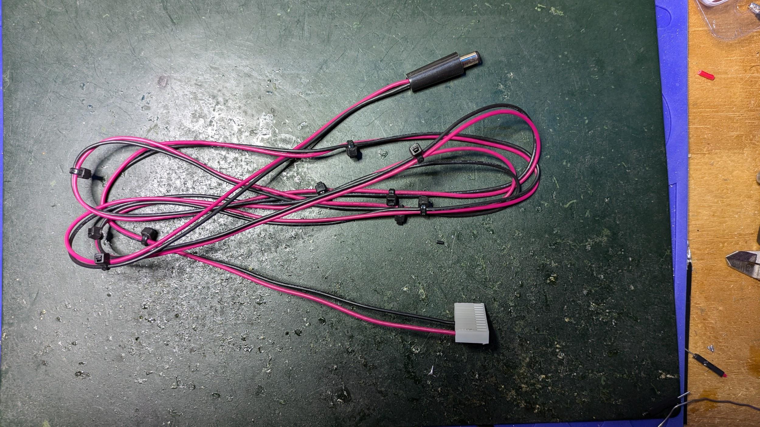
- The Pinlights Power Cable — 13-pin Molex on one end, round DC barrel jack on the other.
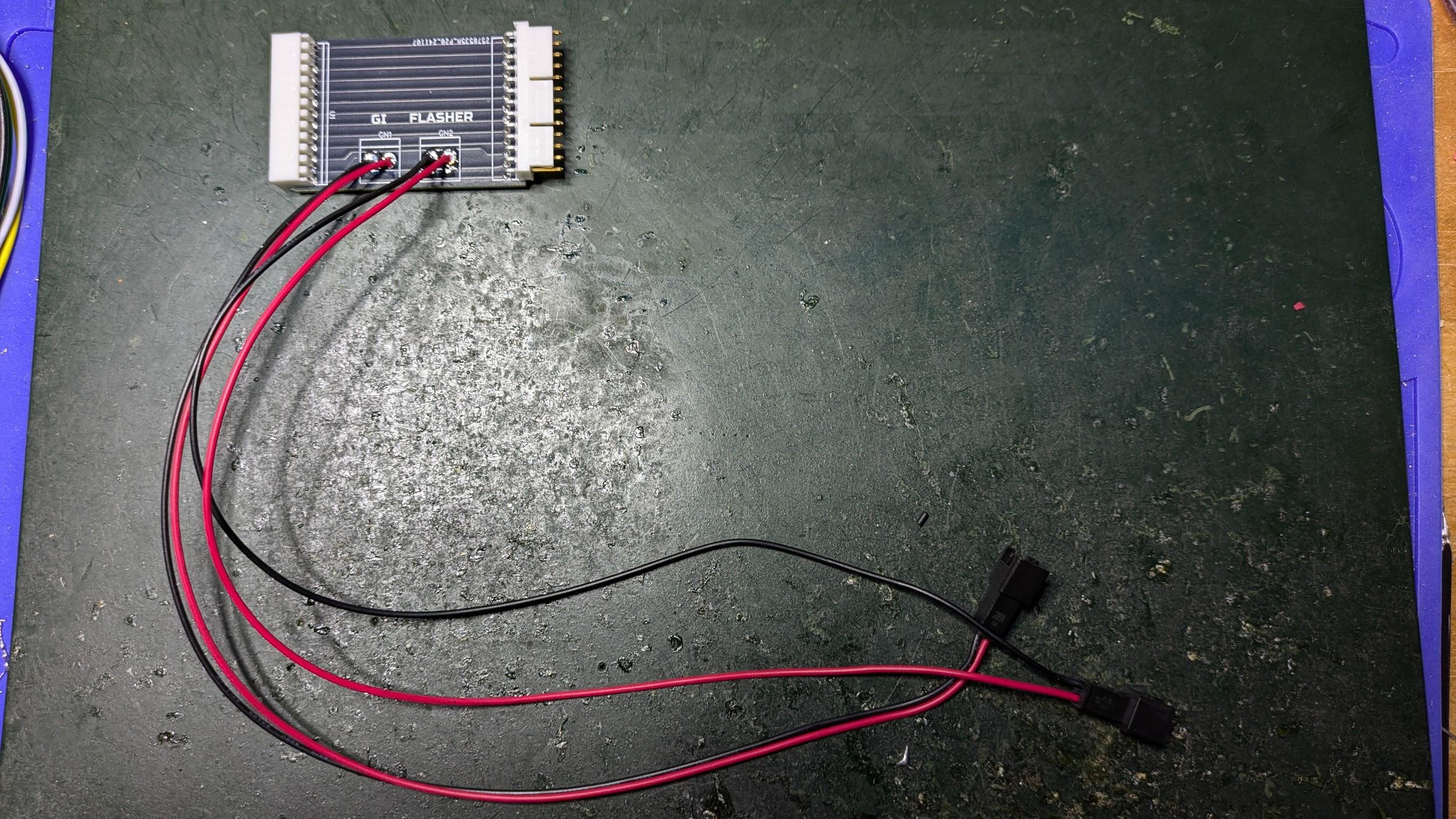
- The Pinlights Signal Interface PCB.
Locate the Cabinet Node Board
With the game powered off and the playfield lifted, find the cabinet node board just inside the coin door on the left wall of the game cabinet.
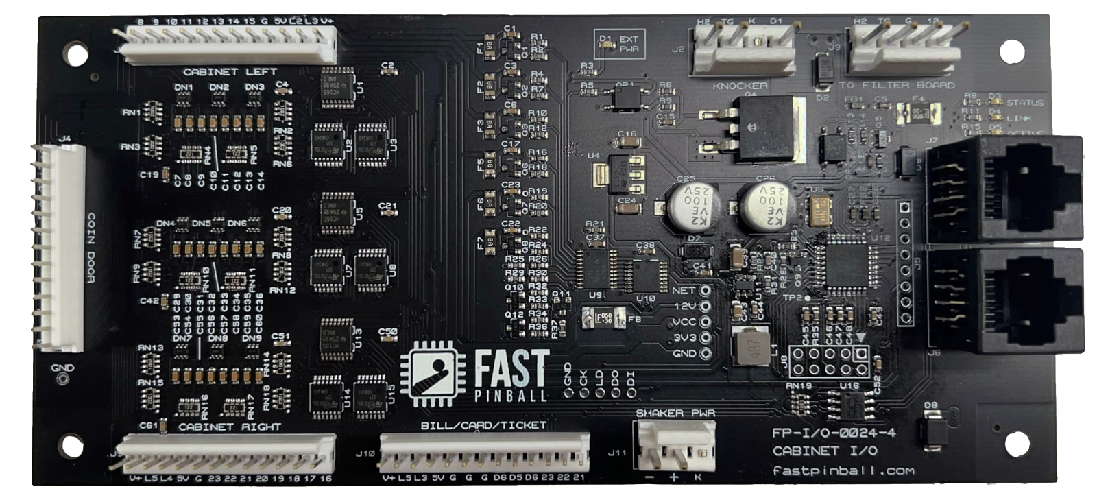
Unplug the Cable at J4
Disconnect the cable currently plugged into the J4 header on the cabinet node board. Set the free end aside — you will reconnect it in the next step.
Insert the Signal Interface PCB Inline
Plug the female connector of the Pinlights Signal Interface PCB into J4 on the cabinet node board. Then plug the cable you just unplugged into the male header on the Pinlights Signal Interface PCB so it sits inline between the node board and the original cable.
Run the GI and Flasher Sensor Cables
Take the two longer red-and-black sensor cables (2-pin black JST on one end, 2-pin white/clear Molex on the other). Connect them to the GI and FLASHER ports on the Pinlights Signal Interface PCB, then run the other ends to the GI and FL ports on the Pinlights Controller PCB respectively.
Connect the Pinlights Power Cable
Plug the 13-pin Molex end of the Pinlights Power Cable into J10 on the cabinet node board. The barrel-jack end powers the Pinlights Controller.
Mount the Light Bars
Mount the Pinlights light bars normally. Consult the pinlights.net/support page for general mounting instructions.
Required game code
You must be running 2024.10.14 code or later for this integration to work.
Questions? Contact [email protected].